
The Carnot cycle, which consists of two isothermal processes and two adiabatic processes, is the most effective heat engine cycle. The most effective heat engine cycle permitted by physical laws is the Carnot cycle.
The processes involved in the heat engine cycle must be reversible and involve no change in entropy to approach the Carnot efficiency. This describes the maximum theoretical efficiency that can be achieved with ideal coolant and insulation properties. Since no real engine processes are reversible and all real physical processes involve some increase in entropy, the Carnot cycle is therefore an idealization.
Interesting Science Videos
What is Carnot Cycle?
A Carnot cycle is a closed thermodynamic cycle that is ideal and reversible.
Isothermal expansion, adiabatic expansion, isothermal compression, and adiabatic compression are the four successive processes that take place. The substance can be expanded and compressed during these operations up to the desired point and back to its initial state.
Heat engines run in cycles. Depending on how each process is carried out, a heat engine’s efficiency will vary. Reversible cycles, or cycles whose constituent processes can all be reversed, are the most effective cycles.
Although, in practice, it is impossible to produce reversible cycles.
A Carnot cycle is significant because it will determine the highest level of efficiency for a heat engine cycle operating between two temperature limits. According to the Carnot principle, the temperature of heat addition and rejection is the only working temperature limit that affects a reversible heat engine’s efficiency.
No heat engine will be more effective than the Carnot cycle when operating within the same temperature range.
Therefore a reversible heat engine’s efficiency is never dependent on the characteristics of the working materials.
History of Carnot Cycle
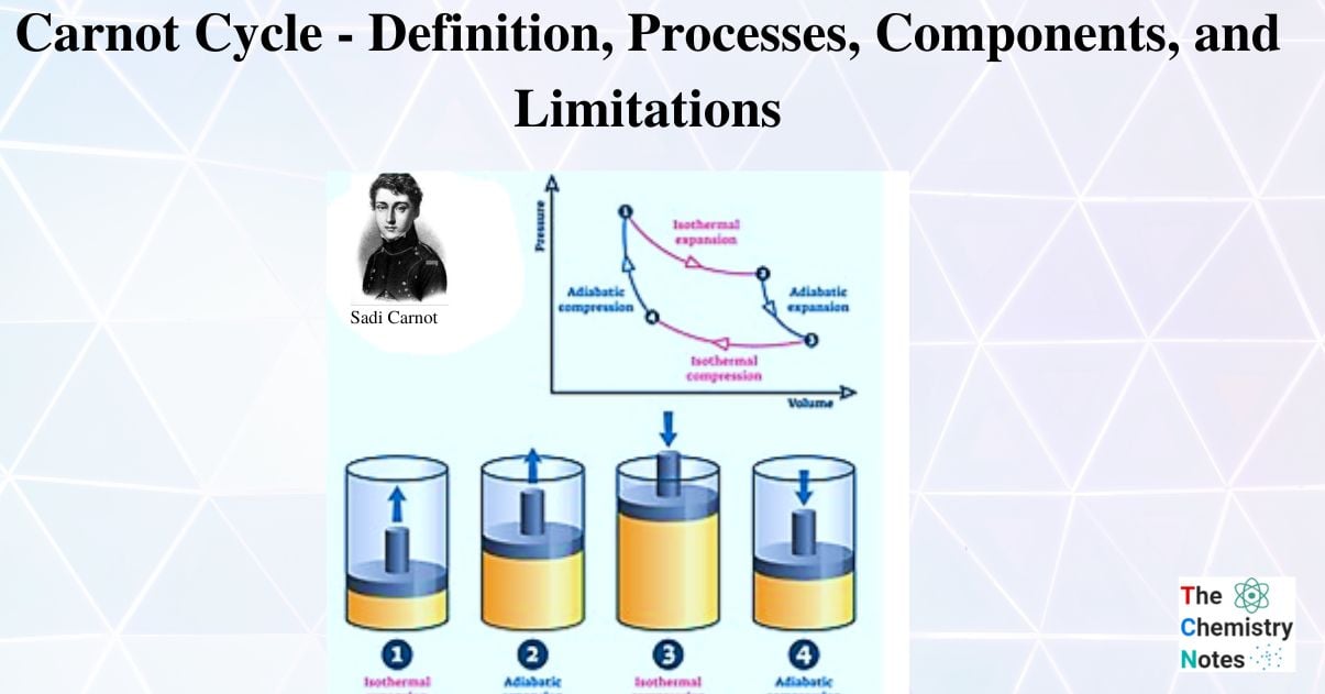
Sadi Carnot (1786–1832), a French engineer, started to become interested in enhancing the efficacy of practical heat engines in the early 1820s. His research led him to propose a fictitious working cycle between the same two reservoirs in 1824; this cycle is now known as the Carnot cycle. The term “Carnot engine” refers to an engine that runs in this cycle.
Benoit Paul Emile Clapeyron enhanced the Carnot engine’s graphical representation in 1834.
Rudolf Clausius investigated the Carnot cycle mathematically in 1857. This research produced the fundamental thermodynamic idea of entropy.
Carnot Cycle Processes
There are four processes of Carnot Cycle:
- Isothermal Expansion
- Adiabatic or Isentropic Expansion
- Isothermal Compression
- Isentropic Compression
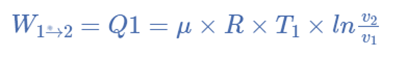
Isothermal Expansion, (Process 1-2)
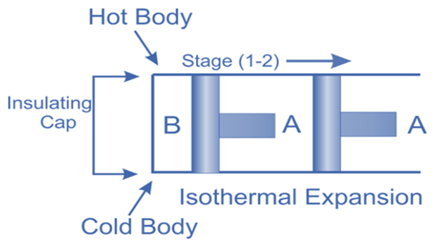
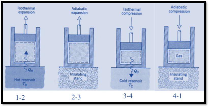
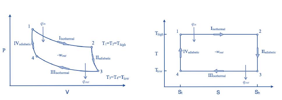
The hot body is brought into contact with the cylinder’s bottom at a higher temperature. From v1 to v2, the air expands practically at constant temperature T1 this means the temperature T2 (at point 2) is equal to the temperature T1. Curve 1-2 on the p-v and T-s diagrams in the figure represents this isothermal expansion. The air completely absorbs the heat that the hot body emits and hence uses it to perform external work.
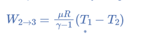
Adiabatic or Isentropic Expansion, (Process 2-3)
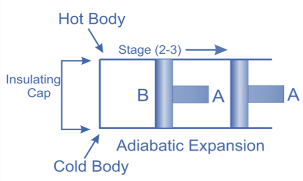
The hot body is removed from the bottom of cylinder B and the insulating cap is brought into contact. It is now possible for the air to adiabatically expand. As a result, curve 2-3 on the p-v and T-s diagrams represent adiabatic expansion.
From T2 to T3, the air’s temperature drops.
Internal energy decreases because the air neither absorbs nor rejects heat.
Isothermal Compression, (Process 3-4)
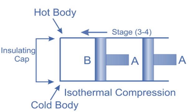
Now take off the insulation cap from the cylinder’s base and bring the cold body into contact with it. From V3 to V4, the air is practically compressed at a constant temperature T3.
This indicates that the temperature (T4) at point 4 is equal to T3.
Hence on the P-V and T-s diagram, curve 3-4, which represents this isothermal compression, is shown.
It would be clear that during this process, the heat is rejected by the cold body and equals the work done in the air.
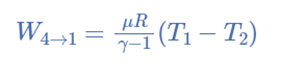
Isentropic compression, (Process 4-1)
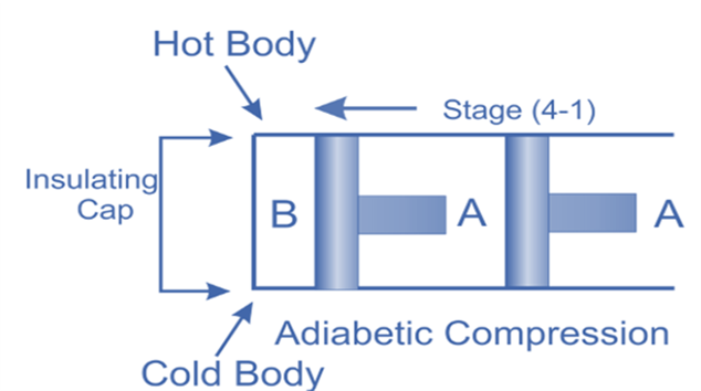
The insulated cap once more is brought into contact with cylinder B’s bottom, and the air is then allowed to be compressed adiabatically.
Hence on the p-v and T-s diagram, curves 4-1 represents the adiabatic compression.
From T4 to T1, the air’s temperature rises. No heat is either absorbed or rejected by the air
Carnot’s Efficiency
Efficiency is a term used to describe how effectively a system or device operates and how well a device produces results. The Carnot Cycle, as was previously stated, is the ideal cycle that provides high and maximum efficiency.
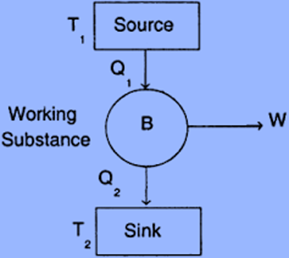
Since the ratio of heat converted into work in a cycle to the total heat supplied to the source is considered the efficiency of a heat engine.
η = Work done/Heat supplied
= (Q1 – Q2)/Q1
= 1 – (Q2/Q1)
If T1 and T2 are the temperatures of the source and the sink, respectively, then (Q2/Q1) η = 1 – (T2/T1)
The engine’s ability to run on Carnot’s cycle must be noted as being challenging.
For the same reason, the isothermal expansion 1-2 will need to be carried out very slowly to guarantee that the air is always at temperature T1.
As a result, it will be necessary to remove the isothermal compression 3-4 very gradually. To get closer to ideal adiabatic conditions, however, adiabatic expression 2-3 and compression 4-1 should be performed as soon as possible.
We are aware that an engine cannot suddenly change its speed in real life.
Eliminating heat losses from conduction, radiation, and other sources, as well as friction between the engine’s numerous moving parts, is challenging. Carnot’s engine is therefore challenging to implement in real life However, such an imaginary engine is used as the ultimate standard for comparing all heat engines.
Components of Carnot Engine
The following are the main parts of the Carnot engine:
- Source
- Sink
- Cylinder
- Standing Insulation
- Piston
Source: A hot body operating at temperature T1 is referred to as a source. The system receives heat from it to function. This heat source has an infinite heat output. You can remove heat from it as you please at a fixed temperature (T1). Even though after extracting a lot of heat, the heat source’s temperature stays constant.
Sink: It is a low-temperature body that maintains its low temperature continuously (T2). Additionally, the sink has limitless heat capacity which indicates that a sink’s temperature is not increased by the heat applied to it.
Cylinder: The wall of the cylinder is non-conductive, and the bottom is conductive. It has a piston that is completely conductible and frictionless. In order to compress the gas, this piston moves up and down. An ideal gas is used as the working medium in the Carnot engine.
Insulating stand: An adiabatic operation is run on an insulating stand. The material used to construct this portion of the Carnot engine is nonconductive.
Piston: It is a reciprocating part that rotates inside the engine’s cylinder. Gas expands and contracts as a result of the piston’s reciprocating motion.
Limitations of Carnot Cycle
- The Carnot Cycle is an ideal cycle which means that it cannot be created and hence it is only a theoretical idea.
- The Carnot Cycle is only used to study heat engines; thus it does not apply to other kinds of technology.
- Although the isothermal process claims that the temperature is constant, the Carnot Cycle explains that the isothermal expansion process will involve the addition of heat, which is not possible.
- Because the Carnot Cycle is not mentioned in the practical engine, heat loss is possible, resulting in the highest efficiency (which is not possible).
References
- https://byjus.com/jee/carnot-cycle/
- https://byjus.com/physics/carnotengine/#:~:text=A%20Carnot%20cycle%20is%20defined,isothermal%20compression%2C%20and%20adiabatic%20compression.
- https://www.sciencedirect.com/topics/engineering/carnot-cycle
- https://web.mit.edu/16.unified/www/FALL/thermodynamics/notes/node24.html
- https://www.theengineerspost.com/carnot-cycle/
- https://www.mechanicaltutorial.com/4-stages-of-carnot-cycle-improving-thermal-efficiency
- https://mechanicalboost.com/carnot-engine/