Atomization is the process of producing atoms available for absorbance measurement. Atomic absorption analysis is based on generating and supply of free analyte atoms in the ground state to light the element’s characteristic wavelength.
Atomic absorption spectrometry, like other spectrochemical techniques, is used to detect element concentrations, usually in liquid form. It is most suited for element analysis in aqueous solutions of dissolved or diluted materials and for samples diluted with other solvents like organic solvents. With the development of AAS, several atomization techniques have been developed.
Atomization is a critical stage in AAS since it determines the sensitivity of reading. The best atomizers produce a significant quantity of homogeneous free atoms. As a result, the atomizer and vaporization methods used determine sample throughput and the detection limit for particular elements. There are various processes of atomization. The two most prevalent atomization procedures are flame atomization and electrothermal atomization.
Flame atomization
The spectrometer’s sample cell, or atomizer, must generate the ground state atoms required for atomic absorption to occur. This entails using thermal energy in order to break the bonds that hold atoms together as molecules. Despite the availability of various alternatives, the flame remains the most common and utilized sample atomizer.
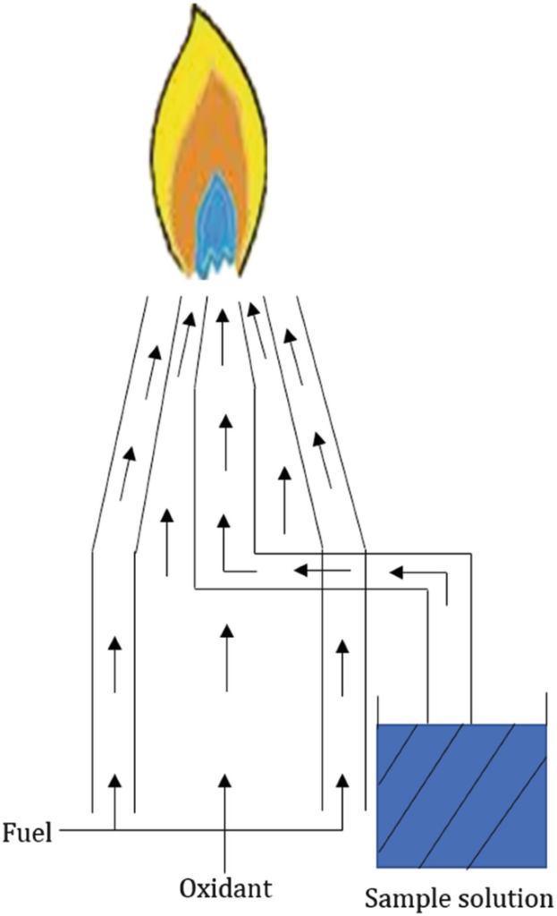
In atomic absorption, flame atomization devices transform analyte solutions into free atoms in the optical path in phases. The primary goal of the sample introduction system is to form an aerosol of the sample in the fuel mixture. This necessitates the formation of an aerosol with an appropriate amount of small droplets to introduce a portion of the sample into the flame without experiencing problems such as a nebulizer or burner blockage. A nebulizer is typically used to make the aerosol. A spray chamber is employed to filter larger droplets from the aerosol.
The chemical composition of the flame determines many subcategories. The flame’s composition is frequently determined by the sample being studied. The flame itself should be safe, have enough energy, be long and smooth, and meet various other criteria. Today, the two oxidant/fuel combinations employed almost exclusively in atomic absorption are air-acetylene and nitrous oxide-acetylene.
Air acetylene
The air-acetylene flame is the preferred flame for determining around 35 elements via atomic absorption. The air-acetylene flame has a temperature of roughly 2300 °C.
Nitrous oxide acetylene Flame
The nitrous oxide-acetylene flame, with a maximum temperature of around 2900 °C, is used to determine the elements that generate refractory oxides. It is also utilized to prevent chemical interferences that may exist in lower-temperature flames. The nitrous oxide-acetylene flame emits a lot of light at particular wavelengths. This can lead to changes in the analytical results for measurements at these wavelengths, especially if the lamp emission for the element of interest is poor. With the nitrous oxide-acetylene flame, only the nitrous oxide burner head can be utilized.
Several elements, including As, Ca, Cr, Mg, Mo, Os, Se, and Sr, can be determined in either the air-acetylene or nitrous-oxide/acetylene flame. Although an air-acetylene flame is useful for these elements, it is not fully effective for all sample types due to inter-element interferences. Using a hotter flame, such as nitrous oxide/acetylene, interferences can be reduced or eliminated by decomposing the chemicals involved.
Flame atomizers are extensively used for various reasons, including their simplicity of use, inexpensive cost, and a long period of use. A flame atomizer accepts an aerosol from a nebulizer and converts it into a flame with enough energy to both volatilize and atomize the sample.
Flame or burner
The flame or burner used in the flame atomization process has a different function. They are:
Nebulizer: Produces a fine mist of the specimen (nebulizes it).
Disperser: A device that delivers minute particles of the nebulized specimen to the flame. The entire structure is constructed of glass.
Burner head: Provides a steady flame for atomization of the elements in the specimen. It has a structure that generates a lengthy flame to ensure an optical path length.
Types of burner
There are two different types of burners usually used in flame atomization. They are:
I. Premix burner
II. Total consumption burner
Premix burner
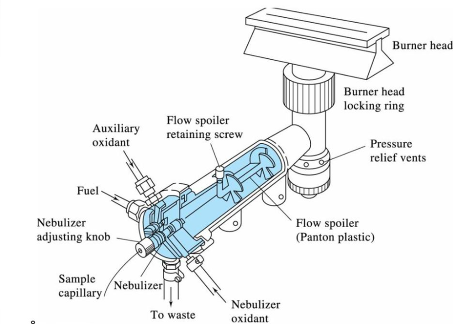
Premix burners were the first specifically designed burners and are also known as laminar flow burners. A premix burner system is made up of two major components: the burner head or nozzle and the gas-air mixing equipment that feeds it. The fuel and support gases are combined in a chamber before entering the burner head (through a slot) and combusting. The sample solution is inhaled through a capillary using the ‘Venturi effect’ using the support gas. Large droplets of the sample condense and drain from the chamber. The minute drops remain to mix with the gases and enter the flame. Only 10% of the droplets condense, leaving 90% to get inside the flame. A drain removes the extra sample from the premix chamber.
So, in the premix burner, a vaporizing chamber produces the aerosol. The aerosol is combined with the fuel gases and the oxidant (carrier), and the resulting gases flow to the burner. The smallest droplets of sample mist, or aerosol, are delivered by the combustion gases to the burner head, where they are atomized. A drain removes the extra sample from the premix chamber.
laminar flow burner
Image source: https://slideplayer.com/slide/13315651/
Advantages of premix burner
I. Adequate flames was obtained.
II. A long path length is obtained.
III. There is no flashback.
IV. A very homogenous mixing of fuel, oxidant, and droplets occur.
V. Larger droplets are filtered out and transferred to a waste container.
Limitations of premix burner
I. Premix burners are typically limited to low-burning-velocity flames. The main disadvantage of the premix burner is that only low-burning-velocity flames can be used.
II. A higher burning velocity than the rate of flow gases leaving the burner causes the flame to travel down into the burner, resulting in an explosion known as a flashback.
III. It is difficult to use high-burning-velocity gases, such as oxygen-based flames.
Total consumption burner
In this system, the fuel and oxidant (support) gases are combined and combusted at the tip of a total-consumption burner. The fuel (typically acetylene), oxidant (usually air), and sample all meet at the base of the flame. The ‘Venturi Effect’, caused by the support gas, draws the sample into the flame. The gas creates a partial vacuum above the capillary barrel, which forces the sample up the capillary. It is split into a fine spray near the tip, where the gases are turbulently combined and burned. This is the standard ‘nebulization’ procedure. Because every drop of aspirated sample enters the flame, or in other words, the sample solution is directly aspirated into the flame, the burner is known as total consumption. So, in total consumption burner, desolvation, atomization, and excitation occurs in the flame.
Total consumption burner
Image source: https://link.springer.com/chapter/10.1007/978-981-15-1547-7_6
Advantages of total consumption burner
I. The total consumption burner can be used to aspirate viscous and ‘high solids’ samples more easily.
II. This burner is suitable for a wide range of flames, including low- and high-burning-velocity flames.
Disadvantages of total consumption burner
I. It is not possible to obtain a uniform and homogeneous flame.
II. As droplet size varies, the intensity of the flame varies.
Disadvantages of flame atomization
I. The main drawback of employing flame atomization for atomic absorption is the inadequate sampling mechanism. Only a little portion of the sample aspirated through the atomization device (approximately 10%) reaches the flame.
II. Furthermore, the sample is diluted with an enormous amount of gas, which transports the aerosol into the flame.
III. Many variables influence the production of atoms in the ground state, including flame temperature, interactions between flame gases, matrix components, and analyte, chemical interferences, and the extent to which the analyte molecular species are dissociated.
IV. Free atoms are only present in the light path for a short period typically 10-4 seconds.
V. The residence time is proportional to the velocity of the flame gases.
Graphite furnace atomization
Analytical sensitivity can be greatly improved by atomizing the entire sample at once and allowing free atoms to stay in the optical path for a greater duration of time. This improves the AA technique’s sensitivity. These advantages are provided through graphite furnace atomization. A graphite furnace atomizer is also known as an electrothermal atomizer
In this atomization, the flame is replaced by an electrically heated graphite tube in an argon chamber. The argon gas protects the graphite tubes from oxidizing too quickly at high operating temperatures and aids in the removal of matrix components and other interfering species from the light path during the drying and ashing processes.
A graphite furnace atomization usually consists of three stages:
Drying: After injecting the sample into the graphite tube, it is dried at or near the boiling point of the solvent (typically between 80 and 200oC).
Charring or ashing: The temperature is raised in the following stage of the furnace program, the ashing step, to remove as much of the matrix material as possible without losing the analyte.
Atomization: The third phase is the atomization process, in which the furnace is rapidly heated to a high temperature to evaporate the ashing stage residues. This results in the formation of a cloud of free atoms in the optical path. During this stage, the absorbance is measured. The temperature of atomization is determined by the element’s volatility.
As a result, electrothermal atomization first dries the sample and evaporates much excess solvent and contaminants then atomizes it, and then rises it to an extremely high temperature to clean the graphite tube.
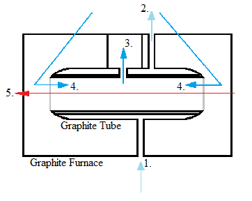
Graphite furnace atomization (electrothermal atomization)
here, (1) external gas flow inlet, (2) the external gas flow outlet, (3) the internal gas flow outlet, (4) the internal gas flow inlet, (5) the light beam
image source: https://chem.libretexts.org/Bookshelves/Analytical_Chemistry/Physical_Methods_in_Chemistry_and_Nano_Science_(Barron)/01%3A_Elemental_Analysis/1.04%3A_Introduction_to_Atomic_Absorption_Spectroscopy
Disadvantages of graphite furnace atomization
I. Graphite furnace analysis times are significantly longer than those used for flame sampling, and fewer elements can be determined by graphite furnace AA.
Platform Atomization
In platform atomization, the platform is mounted on the graphite tube. Because the platform is only supported within the tube at the edges, there is little physical contact between the tube and the platform. The platform’s impact is to delay sample atomization until the graphite tube has attained a stable (high) temperature. As a result, atomization of the analyte from the platform occurs in an environment that is considerably hotter than would have occurred otherwise. One of the platform’s advantages is that atomization at a high-temperature environment allows for more freedom from interferences and background for volatile elements.
Disadvantages of platform atomization
I. The maximum volume of sample that can be emitted onto the platform is 40 µL. Platforms also reduce light throughput slightly, thus aligning the furnace workhead is crucial to achieving optimal light flow.
References
- Akash, M.S.H., Rehman, K. (2020). Atomic Absorption Spectroscopy. In: Essentials of Pharmaceutical Analysis. Springer, Singapore. https://doi.org/10.1007/978-981-15-1547-7_6.
- Hill, S. J., & Fisher, A. S. (2017). Atomic Absorption, Methods, and Instrumentation. Encyclopedia of Spectroscopy and Spectrometry (Third Edition), 37-43. https://doi.org/10.1016/B978-0-12-803224-4.00099-6.
- S. K. Gautam, B. R. Poudel, H. R. Sharma (2016). Concise Analytical Chemistry, National Book Centre.
- https://chem.libretexts.org/Bookshelves/Analytical_Chemistry/Physical_Methods_in_Chemistry_and_Nano_Science_(Barron)/01%3A_Elemental_Analysis/1.04%3A_Introduction_to_Atomic_Absorption_Spectroscopy.
- https://slideplayer.com/slide/13315651/.
- https://www.iitk.ac.in/che/PG_research_lab/pdf/resources/AAS-GTA-reading-material.pdf.
- https://cdn.intechopen.com/pdfs/26275/InTech-Atomic_absorption_spectrometry_aas_.pdf.
- https://www.ipen.br/biblioteca/slr/cel/0151